
Quadrature bias in a Mach-Zehnder modulator, and what the control loop is really holding, Why quadrature sits at half power, the three things that move it, the distortion it causes, and what to ask for on delivery.
Set a Mach-Zehnder modulator at quadrature, and the extinction ratio is excellent on day one. Run it for a few months and it starts to degrade. The device is not broken — the operating point has moved. Every lithium niobate modulator does this. The only question is how fast.
That deserves an article of its own because the consequence is routinely misread. Drift is assumed to cost you a little gain. What it actually costs is waveform asymmetry, and no equaliser gives that back.
1. Why quadrature sits at half power
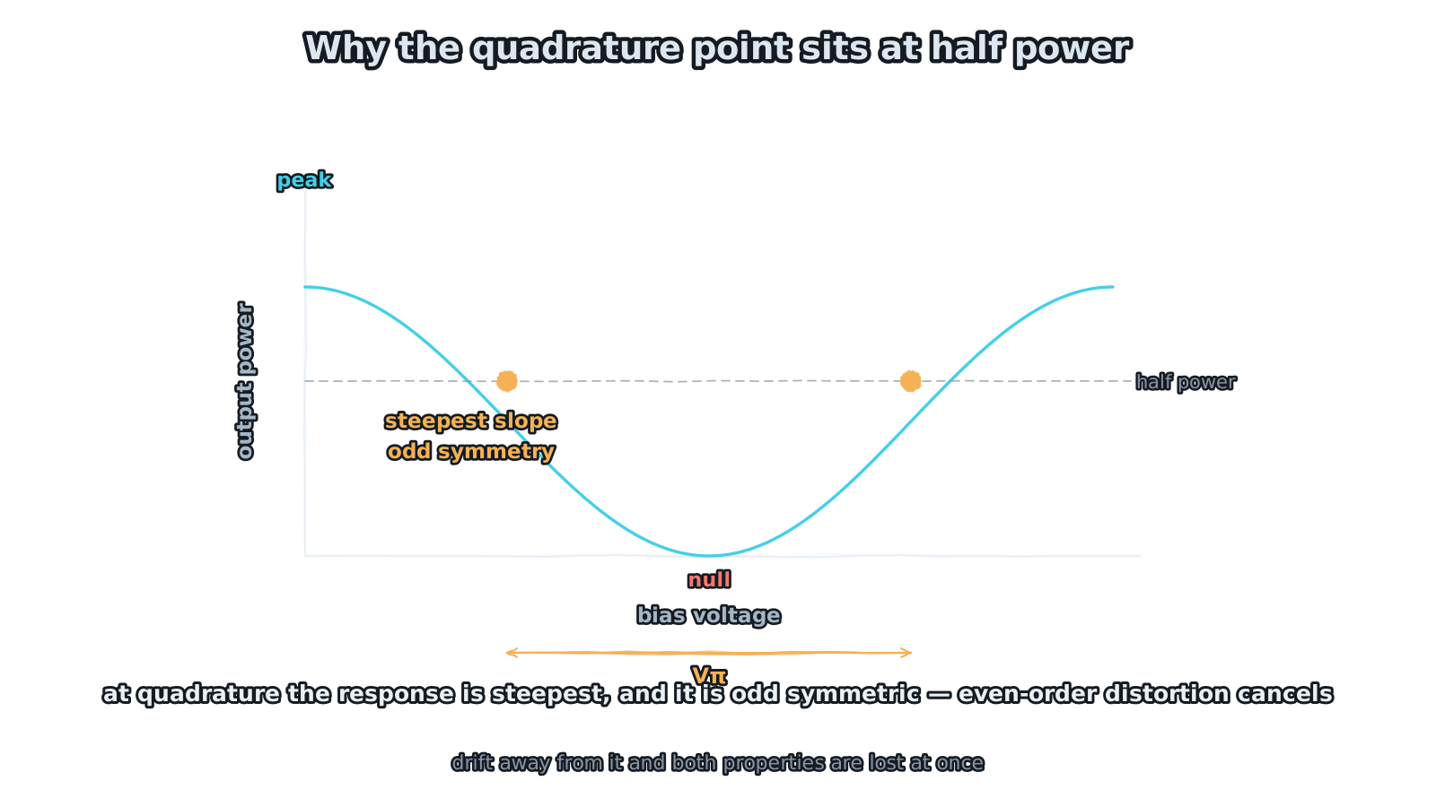
Figure 1 — Why the quadrature point sits at half power
steepest slope, and odd symmetry cancels even-order distortion
The output power of a Mach-Zehnder modulator traces a cosine against bias voltage: zero phase difference between the arms and everything comes out, a difference of π and everything cancels, with a continuum in between. Quadrature bias means sitting in the middle of that curve — at half power.
There are two reasons for choosing that point, and the second matters more than the first.
The first is maximum slope. The curve is steepest at half power, so a given drive voltage buys the largest output swing — the highest modulation efficiency. That is the intuitive one, and the one everyone knows.
The second is odd symmetry. Near quadrature the transfer function is approximately odd about the bias point: shifting up and shifting down produce equal and opposite effects. That property has a very practical consequence — even-order distortion cancels itself out. Second harmonic, second-order intermodulation, all removed by the symmetry itself. Linearity improves substantially, and linearity is a hard requirement in both analogue links and higher-order modulation formats.
So quadrature is not merely the most efficient point. It is the cleanest. And drift takes away not just efficiency but that symmetry.
2. Three things move it
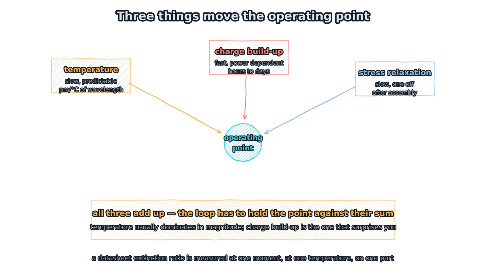
Figure 2 — Three things move the operating point
temperature dominates in size; charge build-up is the surprise
Three mechanisms shift the operating point, and they differ in both size and speed.
Temperature is the largest in magnitude. The refractive index of lithium niobate varies with temperature, so the phase difference between the arms follows; in effect the operating point translates by a few percent of Vπ per degree. It is slow, predictable in direction, and the easiest to compensate — which is why modules carry temperature control.
Charge build-up is the troublesome one. Photorefractive effects and charge migration in lithium niobate establish a built-in field near the waveguide, and that field adds directly to the bias. It scales with optical power — more power, faster — and runs on timescales of hours to days, with a direction that is not fully predictable. Temperature you can model; this one can only be chased with a loop.
Stress relaxation is usually one-off. After die attach, fibre coupling and packaging fix everything in place, material stress releases slowly over an initial period, and the operating point drifts for a while and then settles. Its practical effect is that a freshly assembled module and one that has run for a week are not biased at the same point.
Those three add up, and their sum is what the control loop has to hold against. A datasheet extinction ratio is measured at one moment, at one temperature, on one part: it cannot answer what the value will be in three months.
3. The consequence is not a gain error
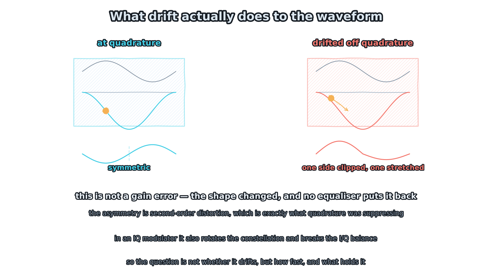
Figure 3 — What drift actually does to the waveform
not a gain error — the shape changed and no equaliser restores it
This section is the point of the article.
At quadrature, a sinusoidal drive produces a sinusoidal output — symmetric above and below. Move the operating point toward the peak or the null and the nonlinearity of the cosine shows through: one half-cycle is compressed and the other stretched, or vice versa. The output is no longer a sine.
The important thing is that this is not a change in amplitude. An amplitude change can be recovered with gain; a change in shape cannot. It is nonlinear distortion, specifically second-order — and quadrature was suppressing even-order terms precisely through that odd symmetry. Move off the point and they reappear.
In a digital coherent system the constellation compresses or rotates and I/Q balance breaks. In an analogue RF link, second harmonic and second-order intermodulation worsen and SFDR drops directly. Neither belongs to the category of gain error, and neither can be recovered by equalisation or post-processing.
So the accurate statement is this: drift consumes linearity margin, not gain margin. And linearity margin is usually the thinner of the two.
4. Closing the loop
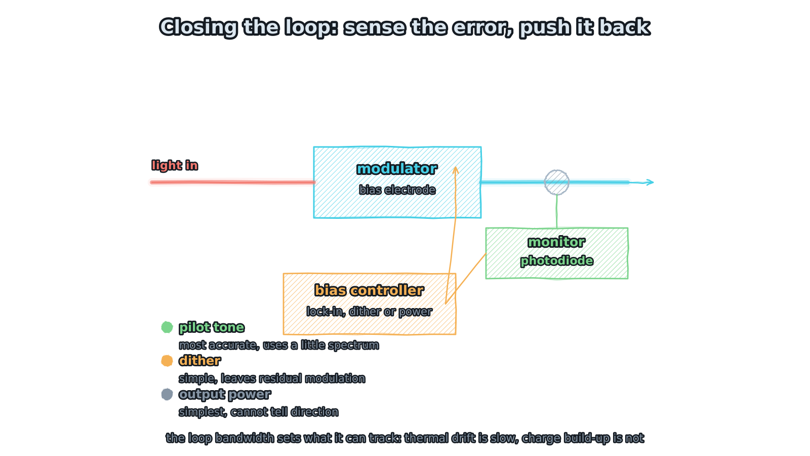
Figure 4 — Closing the loop: sense the error, push it back
pilot tone is most accurate, dither simplest, power cannot tell direction
Since drift is unavoidable, the standard answer is a control loop: tap a little light off the output, let a controller work out the error, and push it back onto the bias electrode.
Three ways to sense the error, each with a trade-off. Pilot tone — superimpose a small low-frequency tone on the bias and detect the error with a lock-in. Most accurate; costs a little spectrum and some extra detection circuitry. Dither — wobble the bias slightly and see which way output power goes. Simplest circuit, but it leaves residual modulation on the output. Output power — watch whether average power equals the target. Simplest of all, with one hard flaw: it cannot tell which way you drifted, because power is an even function about quadrature.
Which one depends on the application. Power monitoring is adequate where cost matters and requirements are loose; a pilot tone is standard wherever linearity is sensitive.
One more parameter that tends to be overlooked: loop bandwidth. It sets how fast a change can be tracked. Thermal drift is slow and a few tens of hertz suffice; charge build-up is much faster, particularly after a power step, and a slow loop will lose lock during that interval. Asking "what is the loop bandwidth, and how long does it take to recover from a power step" tells you more than any static accuracy figure.
5. An IQ modulator has three
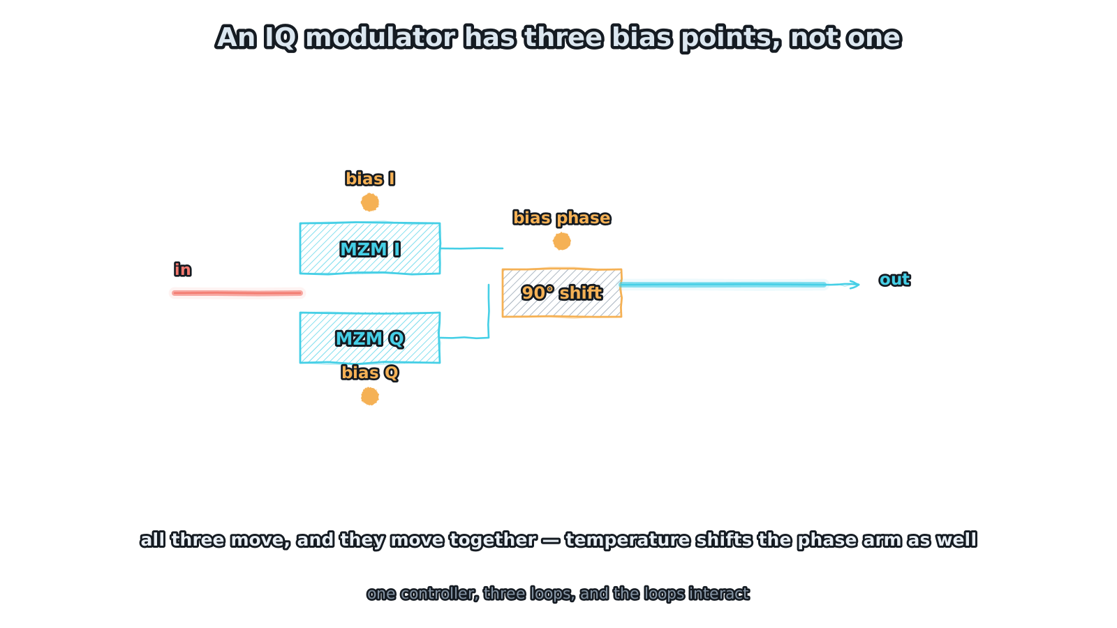
Figure 5 — An IQ modulator has three bias points, not one
all three move together, and they interact
Everything so far concerns a single MZM. An IQ modulator contains two child MZMs plus a phase shifter setting the 90° offset between the arms — so three bias points.
The trouble is that they are not independent. Temperature moves the operating points of both MZMs and also changes the phase of the shifter arm: that 90° offset drifts on its own. When the phase arm drifts, I/Q orthogonality breaks and the two channels leak into each other.
Worse, the three loops interact: adjusting one bias moves the error signals of the other two. Bias control for an IQ device is therefore not three independent loops in parallel but a joint problem — either converged in sequence, or solved by a multi-dimensional controller. That is why IQ bias control is a step harder than single-MZM control.
6. What to ask on delivery
Pulling it together, these are the items worth pinning down at selection or acceptance — rather than the factory extinction ratio.
Drift rate — how far the operating point moves per unit time at rated optical power and maximum operating temperature, expressed as a percentage of Vπ, not as a single "typical" number. Residual distortion — the residual second-order distortion with the loop running, or the equivalent SFDR penalty; that is the number that actually enters the link budget. Loop bandwidth and response time — how long to re-lock after a power step. Temperature range and stability — whether the loop holds lock across the whole operating range or drops out in places. Long-term behaviour — whether charge-driven drift is fast at first and then settles, or persists; that decides whether pre-ageing at the factory is warranted.
That last one is often skipped, and it is what determines field behaviour. A device with an excellent factory extinction ratio that degrades visibly after three months is less useful in practice than one with unremarkable initial numbers that the loop holds firmly.
Closing
Bias drift is common to every lithium niobate modulator. It is not a defect and should not be treated as one to be avoided. It follows from the material; what engineering has to do is quantify it, hold it down, and count it at acceptance.
Getting clear on that changes how datasheets get read: not the initial extinction ratio but the residual distortion once the loop is running; not static accuracy but drift rate and loop bandwidth. The first is a photograph of one moment. The second is how the product behaves across its whole life.
Quadrature buys efficiency, but it also buys the linearity that comes from odd symmetry. Drift takes the second one away — and the second one cannot be recovered.